GUI Design
The UT library supports Single Document Interface (SDI), Tabbed Document Interface (TDI), and Multiple Document Interface (MDI) models. Under Windows, the MDI model is implemented in its usual form for that platform, with all of the windows for a given project appearing within a single parent MDI frame window, with a single menu bar in the MDI frame. Under MacOS, the whole system uses an application-centric model which is essentially MDI, at least in terms of how the menu is managed, although there is no MDI frame window. Under Linux, each window has its own menu bar, with no MDI paradigm at all. Only on Windows is the MDI selection explicitly supported. On MacOS and Linux, selecting MDI mode is supported but has no effect, being unavailable on Linux and the only mode supported by MacOS.
In MDI mode, windows can be TDI containers, so the two are not really mutually exclusive.
Under windows, the MDI or not selection should usually be a user preference. On all platforms, the TDI or not selection should also usually be a user preference. Text editors are a perfect example of when and why the model should be a user preference: each model has its own strengths and weaknesses which manifest themselves depending on how the user prefers to work. The UTgui library is designed to make the way an application is coded almost completely transparent across all three models. The application code does need to manage whether a document is embedded in a window or is a view in a TDI container, but the code required is minimal. Application code should not not create window subclasses, instead creating tasks that work with the window and view objects which are embedded into a window. This is consistent with the Model/View/Controller paradigm. Avoiding inheritance from the Window_t class is especially important so that based on user preferences, a document can be presented in an SDI document window, TDI child view, which is not even a window at all, or an MDI child window. This is why even though the UTgui library uses an object-oriented design, the Window_t class's virtual functions are private, instead relying on task notification function registrations.
Multithreaded GUIs (or lack thereof)
While it would be nice to be able to have multiple GUI message loops (threads) to prevent one window from blocking and locking up other unrelated windows that could be running in other threads, GTK+ is more or less a de facto standard for Linux GNOME, one of the UT library's main target platforms, and despite claims to the contrary, GTK+ does not support multithreaded GUIs. The MacOS Cocoa interface is also built on the notion of a single GUI thread, so with Windows being the only popular platform with decent multithreaded GUI support, it makes sense to impose this restriction. Doing so actually makes it much easier and more efficient to manage view to window to application event dispatch hierarchies, so this is actually beneficial.
Avoiding GUI Lockup
An unresponsive GUI is very common, but that is a telltale sign of a poorly designed application, which is completely unacceptable. The UTgui library restricts coding practices which result in an unresponsive GUI by imposing reasonable limits on the amount of time that can be spent dispatching messages. Exceeding those limits will result in an assertion failure in debug builds, although not when running in the debugger since stopping and single stepping guarantee that the limits will be exceeded. Release builds are not subject to those checks. A perfect example of the need for message dispatch time limits would be load or save document commands, the response to which is to synchronously read or write the contents of the model. Normally, the load or save operation would proceed rapidly. Unfortunately, I/O stall events are common, especially when reading from or writing to a network drive. It is therefore recommended that load and save operations be performed by the controller task using File_t or better yet, BufferedFile_t in asynchronous mode relying on FileOpenCompleteMessage_t, FileReadCompleteMessage_t, and FileWriteCompleteMessage_t to drive the load or save operation incrementally to completion. Likewise, network socket operations should be performed asynchronously whenever they are performed from a GUI thread.
As a load operation is progressing, the controller must ensure that the partially populated model is unavailable to the view. The view components must also be designed to handle the absence of a model and should present a progress indication for the load operation. The user should also be able to cancel the load operation, perhaps by closing the window which would have displayed the model to the user upon completion of the load operation. During save operations, a progress indication should likewise be displayed, and the controller should ensure that the model is read-only for the duration of the save operation. If the model is to be accessed from helper threads, a MultiReaderMutex_t can be useful.
Model View Controller
The UTgui library's GUI implementation is designed to facilitate and encourage the Model/View/Controller paradigm for GUI design. The model, view, and controller should all operate in a single thread. Worker threads can be created, to which execution can be deferred, but at a fundamental level, the model, view, and controller all operate in the main thread, in the App_t class which is derived from MessageLoop_t. The controller will be a Task_t subclass installed into App_t.
The controller controls all aspects of the model and its presentation to the user. The controller task should own the model and be responsible for deleting it when appropriate. The controller task should also own one or more Window_t and View_t objects (embedded in Window_t objects) responsible for presenting to the user the contents of the model and, if appropriate, facilitating manipulation of the content of the model by the user. The controller can and probably should own any number of other helper tasks which can be likewise installed into App_t. This will help keep the application code nicely organized.
General Design, Object Roles and Relationships
Every GUI-related controller task must be installed into a the App_t message loop. The following subsections describe the object roles and relationships needed to implement an application with each model.
Application
An application-defined subclass of App_t provides the message loop in which the entire GUI runs. The model selection and application menu are set here. A window cannot be created until App_t::Main has been called. Consequently, when the application object has been created, a message should be posted asynchronously to the application controller task, which triggers it to create the first window.
Application controller
An application controller task should be created by and owned by the App_t subclass. Often, this controller will own "projects". If an application only deals with a single document, that document would represent a single project. Because a project can contain multiple documents, the term project is used to refer to one complete model, its window(s), view(s), and controller(s).
Any design should have a clear hierarchy of ownership. The application-defined subclass of App_t is the root of this ownership hierarchy. It owns the application controller, which in turn owns one or more project controllers. The project controllers own the models for the projects.
The application controller is responsible for deciding when the applicaton should quit. This would typically be when the last window has been closed. Because the application controller shouldn't know about windows though, from its perspective when the last project has been deleted, the application should quit. The exception is MDI mode (available on Windows, and always the case on MacOS), because the user still has a way to tell the application to quit, or to open a new document and continue working.
Project controller
A project controller should own the model for a project. The project controller would typically own any number of subordinate controllers to organize the code. This aggregate of controllers owns all of the windows and views, organized in whatever way makes the most sense for the application's design. Ownership of subcomponents of the model might be organized to be owned by subordinate controllers as well.
When a window is closed by the user, a controller should receive the quit request message and delete the window, which then results in the window actually being closed as seen by the user. Alternatively, if a window has unsaved content, the controller can display a dialog prompting the user to save or discard the unsaved edits.
A project's document(s) are displayed by View_t subclasses installed into a Window_t or Window_t subclass. A project controller or one or more of its subordinate controllers should owns the windows and views.
Windows
From a coding perspective, a window is basically just a container for views and a menu context. When TDI mode is not enabled (usually a user preference) a root window will present the root display for a project in one or more child views. In TDI mode, however, a root window might contain tabs for multiple documents.
In that case, the window will contain a TDIContainer_t view, and its controller should own one or more project controllers. Therefore, in TDI mode, the rule of thumb that the application controller owns one or more project controllers breaks down. Instead, the project controller owns TDI window controllers, each of which represents a window with a TDI container. Each of these TDI window controllers then owns one or more project controllers.
Windows can be subordinate to each other. This is a reflection of an underlying ownership relationship at the controllers level. The subordinate relationships dictate the behavior of menus and modal dialogs.
Menus
In order to accommodate an application menu which is displayed in MDI mode in a state where there are no actual windows open (MDI mode on Windows, always on MacOS), a menu as seen by the user has two parts: an application part and a window part. These two parts are merged to present the menu to the user, either in the MDI frame under Windows if in MDI mode, the application menu at the top of the screen under MacOS, or in the window itself for all other cases.
Any given window may have a menu, or not. If no menu has been created for the active window, then in MDI mode, the global menu will display a merger of the application menu and the menu of the window menu for the first window which has a menu when traversing from the active window to the window which it is subordinate to, and on up until a root window is found which isn't subordinate to any other window.
An application menu must be created before any of the following actions can be performed:
- Calling App_t::SetMDIMode
- Creating any windows which contain menus
- Calling App_t::Start
If the application menu contents are changed, then the menus for all windows containing menus will be updated.
Modal windows
TBD, but driven by subordinate relationship
Floating windows
TBD, but an application-level mechanism for registering floating window types, layout, etc. Can dock into docking-enabled windows except in Windows MDI mode (there, only in the MDI frame). Floating window types always have a fallback view for when there is no content to display.
Windows, the Root View, and Menus
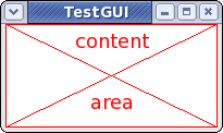
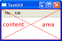
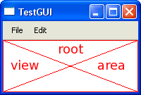
Every window except for a splash screen has some sort of frame decoration, whether it's a simple border on a dialog box, or window title bar and left, right, and bottom frame on a normal document window. The area inside the decorative frame is referred to as the content area. The content area's edge coordinates are expressed in screen coordinates. The entire content area is occupied by a root View_t, except any portion which is occupied by a menu bar if one has been added to the window and is displayed in the window for the target platform. These relationships can be visualized as follows. Docked floating windows also consume window space encroaching into the content area of a window in a manner similar to menus, but on the left, right, bottom, or top (below the menu if applicable). When not docked, floating windows contain a root view as well, but the floating window itself is an abstraction which is not accessible to application code.

View Hierarchies
View_t objects are arranged in a parent/children hierarchy. Every window contains a single root view, which can contain one or more children. The root view always occupies the entire area of a window inside of its frame decoration (excluding a menu bar in the window or docked floating windows, if applicable). The size constraints of the root view dictate the size constraints of the parent window. ViewContainer_t views can contain one or more child views which are displayed within the container's display area. The arrangement of those views, both in initial layout and during resize operations, is determined by the container. The size limits of a container are typically, though not always, a function of the arrangement and size limits of the child views. There are several types (subclasses) of containers provided by the UT library, intended to make view creation easy.
Hierarchical Coordinate Systems
In hierarchies of coordinate systems, like screen to window and window to view, each area has two representations: parent coordinates and local coordinates. In order to avoid confusion, a rectangle in its parent coordinate system is referred to as the frame. To keep that in focus, the term pframe is used in the UT library interface. The same rectangle in its own local coordinates is defined by its bounds. To keep that in focus, the term lbounds is used in the UT library interface. Think of it this way: if a picture is hanging on a wall, where it hangs on the wall is determined by where its frame is hung. The picture itself is a canvas, and the canvas has a boundary constrained by the frame.
The highest level coordinate system is that of the display, typically comprised of one or more monitors (the only exception being embedded systems). The nominal case is one monitor, with one display exactly matching the monitor's selected resolution. Root-level windows exist within a display, and the frame of the window is specified in the display's coordinate system. Because the frame of a window depends on the target platform's window decoration theme, the frame is irrelevant and not accessible. A window's position is specified by its content area, which is a Rect_t whose coordinates are in the screen's coordinate system, as a content area pframe.
As discussed above, every window has a root view. Technically, the root view also has a frame, but that is private to the UT library internals, so that the library can account for how menus are presented on the target platform. Relative coordinate systems become relevant in that the contents of the root view are managed in the root view's relative coordinates. The upper left corner of the root view's contents, in its relative coordinate system, is at (0,0). Any views which are children of the root view have frames specified in the root view's relative coordinate system. Any time the term "frame" is used in the UT libraries, it refers to parent coordinates.
Each of those views may, in turn, have child views. At each level of the hierarchy, a view has its own internal coordinate system which is relative and independent of its parent's coordinate system. That coordinate system always has an origin (the upper left corner) of (0,0) for the view's local coordinate system. This, the lbounds rectangle has left and top values of zero. The only exception to this rule is a View_t subclass, Viewport_t.
Viewports
A viewport is a special type of view whose visible origin is not necessarily (0,0). A perfect example for its usefulness would be where a view contains vertical and horizontal scroll bars as child views, and a third child view (image view) which shows an image that is larger than what can be shown in the image view. As the scroll bars do their job and scroll the image, what they really are doing is changing the image view's visible origin, moving that origin around the underlying image. The AutoScroll_t class is useful for this purpose.
The origin for a viewport's internal, relative coordinate system is returned or set using the Viewport_t::ViewOrigin and Viewport_t::SetViewOrigin functions. The origin dictates what portion of the viewport's underlying content will be shown inside of it, and determines the top left corner of the lbounds rectangle. One can think of the viewport/content paradigm in terms of showing a part (perhaps all) of the content through the view. The upper left corner of the content is always at coordinates (0,0), regardless of whether that corner is visible. The upper left corner of the visible content is always at the origin. The underlying content size is returned or set using the Viewport_t::ContentRect and Viewport_t::SetContentRect functions. The visible content rect can be obtained using the Viewport_t::VisibleLBounds function. The rect returned by that function always has a (left,top) corner equal to the viewport origin. This can be visualized as follows:
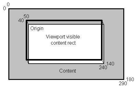
If it is the root view, A viewport's content rect should not be confused with a window's content area, thus the use of the terms content and visible content for viewports and content area for windows.
Coordinate Systems Defined
Within the field of software engineering, there exist a variety of designs for dealing with coordinate systems, particularly in regard to where the edges of a rectangle fall relative to what is visible to the user in the rectangle and what lies one pixel outside the visible portion. In order to facilitate scaling, antialiasing, and to simplify and clearly define the rendering alignment of lines with odd or even pen widths, the UT libraries use floating point numbers for coordinates, with only a final conversion to integer form needed when rendering. Because a display is a grid of pixels though, the meaning of "width" and "height" is somewhat ambiguous. Mathematically, width is right minus left, so a rectangle from (0,0) to (3,2) would have a a width of 3 and a height of 2. But right is 3, and the right side of the rectangle should be displayed. Therefore, the rectangle with width 3 occupies four pixels at x positions 0,1,2,3. This can be visualized as follows:
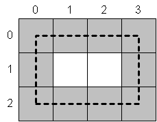
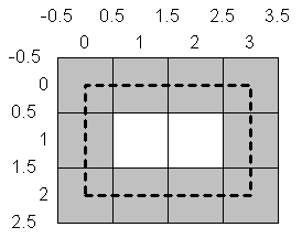
The solution to this apparent contradiction is to take pen width into consideration. A pixel at (0,0) is considered by the UT library to be, in an abstract sense, a rectangle spanning -0.5 to +0.5 in both axes. Explicitly declaring the pen width to be one, the visualization above can be redrawn as:
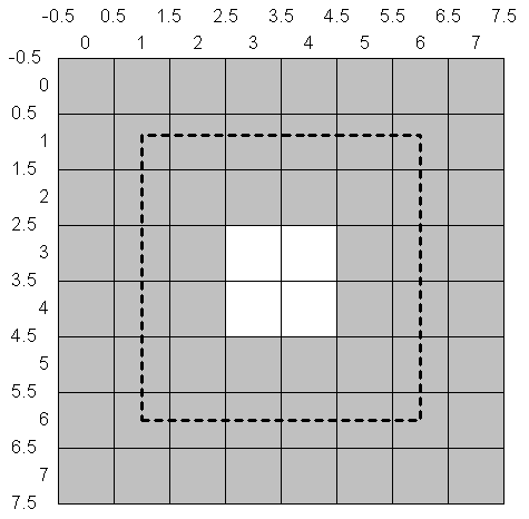
Consistency is thus maintained, even with other pen widths. Here, width and height are 5 and pen width is 3:
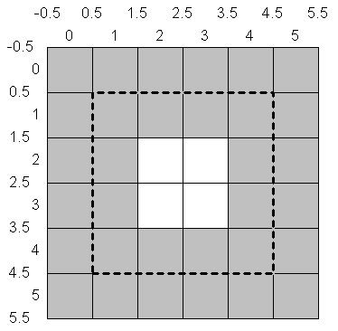
This concept also makes it easy to deal with pen withs that are not odd numbers, by simply defining a rectangle's edges as being at a multiple of 0.5, but not a multiple of 1. Here, left and top are 0.5, right and bottom are 4.5, and pen width is 2:
When coordinates are treated in this manner, mathematical width and height, pen width, and pixel alignment fall into place in a coherent way, with pixel width being the mathematical width plus the pen width. This is how the UT libraries treat coordinates. It is therefore important when dealing with pen widths that are a multiple of two to stick to vertices with x and y coordinates being an integer plus 0.5 unless there is a good reason to do otherwise. When even pen widths are used with antialiasing and integral coordinates, a line will actually span three pixels, with the single pixel center line being at full alpha, and the pixel-width line to either side of center being at half alpha. Without antialiasing, an even width line rendered on an integer coordinate will spill over to the right and/or bottom.
This system extends back to the definition of view frames and content sizes. In those cases, coordinates deal in pixels, which are implicitly 1x1. The "pen width" for any given row or column in a raster is 1. Thus, if a view has a frame in its parent's coordiates of (200,100) to (203,102), the width is 3, height is 2, but it actual coverage is 4x3 pixels, which fits the interpretation that pixel width is the mathematical width plus the pen width of 1 for a pixel.
This system also extends to the underlying content. In order to display a 4x3 image, the content width and height (as set by Viewport_t::SetContentRect) should be 3x2.
 1.6.1
1.6.1